
63 · 71 · 80 · 90
Frames 63–90
Compact machinery, pumps, fans, conveyors and commercial equipment.
AC motors · Product information
IEC induction motor solutions from 0.12 to 55 kW across frames 63–225, available in IE2, IE3 and IE4 configurations and selected around the driven equipment, operating duty and installation requirements.
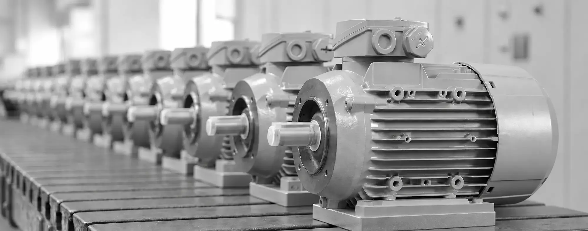
Core asynchronous motor range
Common 2-, 4-, 6- and 8-pole configurations for fixed-speed or inverter-fed duties. Final ratings, efficiency, dimensions and availability are confirmed against the application.
| Parameter | Core range | Selection note |
|---|---|---|
| Rated output | 0.12–55 kW | Higher outputs by engineering review |
| IEC frame | 63–225 | Frames 250–355 considered project by project |
| Efficiency | IE2 · IE3 · IE4 | Final class confirmed by rating, supply and destination market |
| Pole configurations | 2 · 4 · 6 · 8 pole | Speed and starting performance matched to the driven load |
| Operation | Fixed-speed or inverter-fed | Duty and VFD compatibility confirmed at selection |
| Mounting forms | B3 · B5 · B14 · B35 · B34 | Availability depends on frame and construction |
63 · 71 · 80 · 90
Compact machinery, pumps, fans, conveyors and commercial equipment.
100 · 112 · 132
General industrial machinery, process equipment and continuous-duty systems.
160 · 180 · 200 · 225
Medium-duty industrial equipment, larger pumps, fans and material handling.
Project-specific requirements: Outputs above 55 kW and larger IEC frames from 250 to 355 can be considered where the application and supply requirements justify a dedicated engineering review.
Representative 50 Hz selection data
Use frame, output, pole count and voltage class for initial routing. Final full-load current, efficiency, dimensions and available winding are confirmed for the selected motor.
| IEC frame | Typical output | Typical voltage | Poles | Typical full-load speed | Rated torque envelope | Efficiency | Protection |
|---|---|---|---|---|---|---|---|
| 63 | 0.12–0.25 kW | 230/400 V; 400/690 V* | 2 / 4 / 6 | ≈2,800 / 1,400 / 900 rpm | 0.4–2.6 N·m | IE1–IE3 | IP55 typical |
| 71 | 0.18–0.55 kW | 230/400 V; 400/690 V* | 2 / 4 / 6 | ≈2,800 / 1,400 / 900 rpm | 0.6–5.8 N·m | IE1–IE3 | IP55 typical |
| 80 | 0.37–1.1 kW | 230/400 V; 400/690 V* | 2 / 4 / 6 | ≈2,850 / 1,400 / 900 rpm | 1.2–11.7 N·m | IE2–IE4 | IP55 typical |
| 90 | 0.75–2.2 kW | 230/400 V; 400/690 V* | 2 / 4 / 6 | ≈2,850 / 1,430 / 930 rpm | 2.5–22.6 N·m | IE2–IE4 | IP55 typical |
| 100 | 1.5–4.0 kW | 230/400 V; 400/690 V* | 2 / 4 / 6 | ≈2,880 / 1,440 / 950 rpm | 5–40 N·m | IE2–IE4 | IP55 typical |
| 112 | 2.2–7.5 kW | 230/400 V; 400/690 V | 2 / 4 / 6 | ≈2,900 / 1,450 / 960 rpm | 7–75 N·m | IE2–IE4 | IP55 typical |
| 132 | 5.5–15 kW | 400/690 V typical | 2 / 4 / 6 | ≈2,930 / 1,460 / 970 rpm | 18–150 N·m | IE2–IE4 | IP55 typical |
| 160 | 11–37 kW | 400/690 V typical | 2 / 4 / 6 | ≈2,950 / 1,470 / 980 rpm | 36–360 N·m | IE2–IE4 | IP55 typical |
| 180 | 18.5–55 kW | 400/690 V typical | 2 / 4 / 6 | ≈2,960 / 1,480 / 985 rpm | 60–535 N·m | IE2–IE4 | IP55 typical |
| 200 | 30–90 kW | 400/690 V typical | 2 / 4 / 6 | ≈2,970 / 1,485 / 990 rpm | 100–870 N·m | IE2–IE4 | IP55 typical |
| 225 | 45–110 kW | 400/690 V typical | 2 / 4 / 6 | ≈2,975 / 1,490 / 990 rpm | 145–1,060 N·m | IE2–IE4 | IP55 typical |
Selection basis: Voltage and winding depend on output and market. 230/400 V is common on smaller IEC motors; 400/690 V becomes more common as output increases. Frames 250–355 remain available by project review rather than being included in this representative table.
Mechanical integration
Mounting availability depends on frame size, construction and application requirements.
Horizontal foot-mounted arrangement for machinery bases and common industrial installations.
Flange-mounted arrangement for direct integration with pumps, gear units and driven equipment.
Compact face mounting where the available installation envelope is restricted.
Combined foot-and-flange configuration providing greater installation flexibility.
Combined foot and compact face mounting for application-specific equipment interfaces.
Define the right configuration
These inputs establish the correct frame, performance and construction route. Hover, focus or tap each item for the engineering implication.
Beyond the standard frame
Where a standard motor does not fully satisfy the equipment, SDT can support changes to performance, voltage, frequency, shaft, mounting, enclosure, protection, thermal design and connection arrangements.
IEC motor enquiry
Provide the required output, speed, supply, efficiency class, frame or envelope, mounting, environment and duty cycle for an initial engineering review.