Slotless Motor
Motor construction selected around diameter, speed, torque, thermal conditions and service-life target.
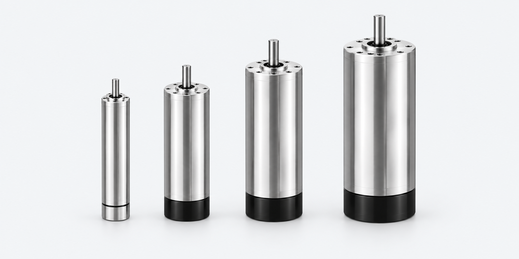
Slot-free stator · smooth brushless motion
Electronically commutated motor and drive platforms for compact applications requiring smooth torque, low noise, high speed and long operating life.
Dedicated brushless architecture
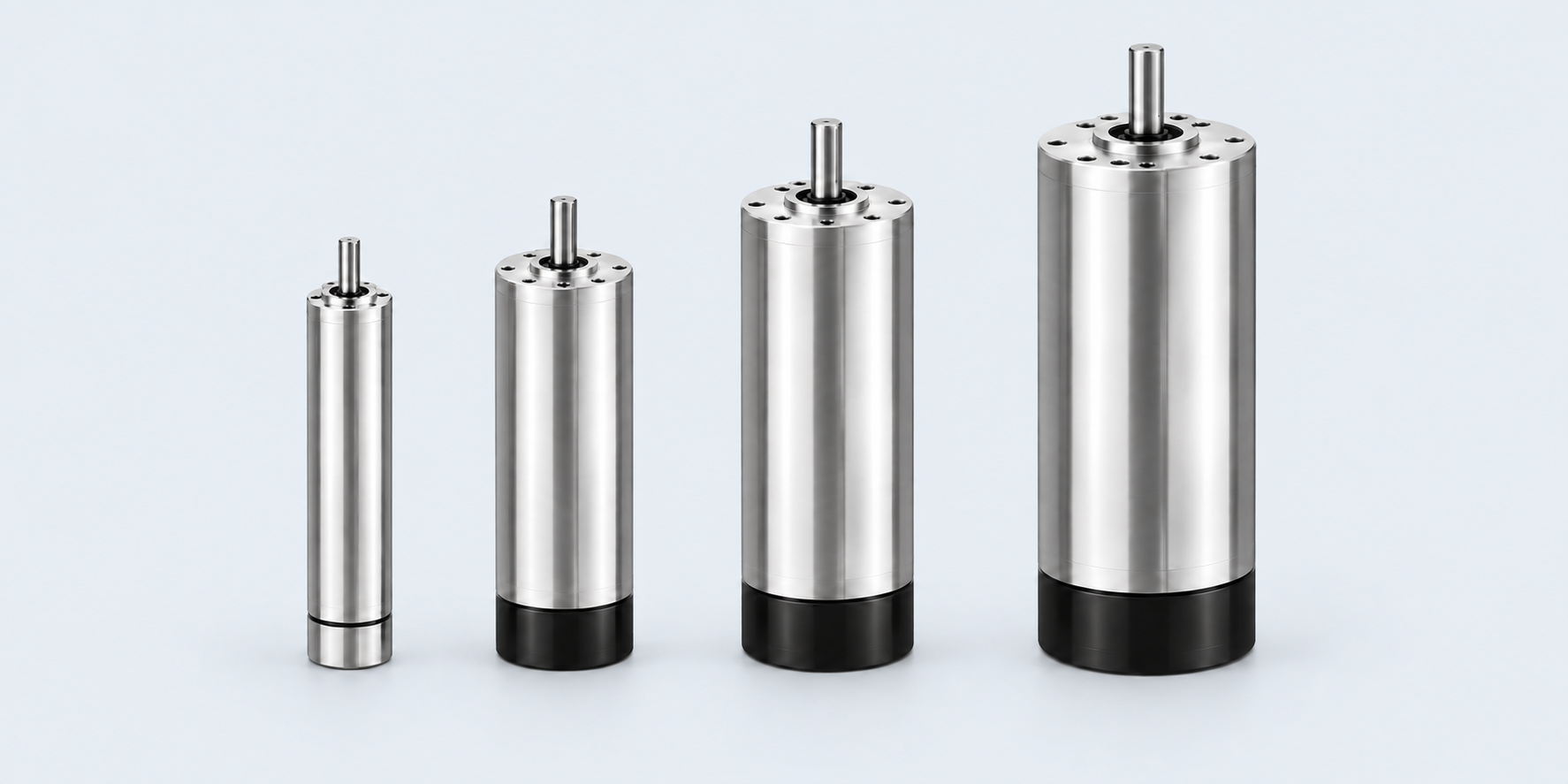
Removing conventional stator teeth and slots reduces cogging, torque ripple and magnetic noise. The result is a compact brushless platform suited to continuous precision motion.
Motor construction selected around diameter, speed, torque, thermal conditions and service-life target.
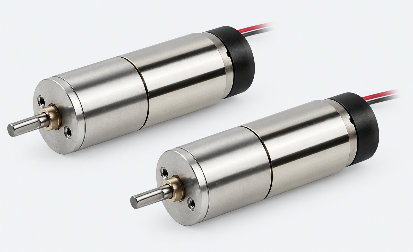
Hall sensors, encoder and electronic controller matched for commutation, speed or position regulation.
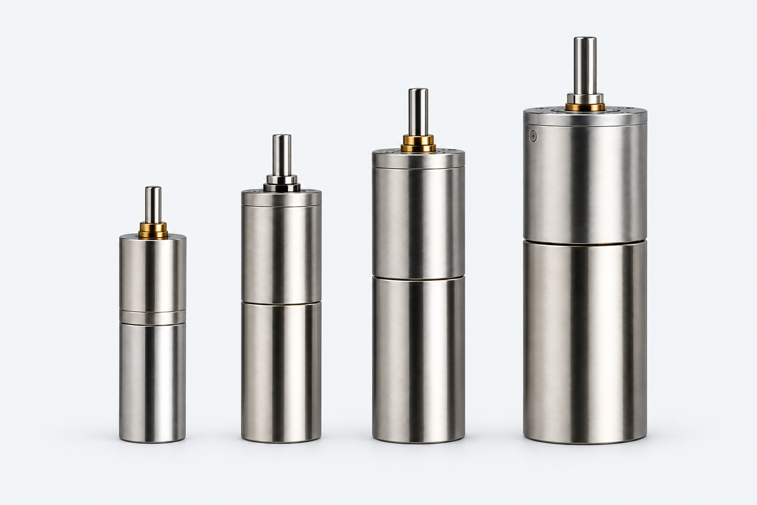
Inline or angular gearhead, shaft and mounting interface configured as one motion assembly.
Representative selection data
The 16–80 mm reference platforms cover compact high-speed duties through to higher-torque motor-and-drive systems. Configurations up to 87 mm are developed against the required winding, length, cooling and controller.
| Motor diameter | Nominal voltage | Rated power | Typical speed | Continuous torque | Peak torque* | Maximum efficiency | Typical length |
|---|---|---|---|---|---|---|---|
| Ø16 mm | 12–24 VDC | 20–50 W | 15,000–55,000 rpm | 5–25 mNm | 15–75 mNm | 80–90%+ | 30–50 mm |
| Ø22 mm | 12–48 VDC | 30–100+ W | 10,000–50,000 rpm | 20–50 mNm | 60–150 mNm | 85–91% | 35–60 mm |
| Ø26 mm | 12–48 VDC | 30–100 W | 8,000–30,000 rpm | 30–70 mNm | 90–210 mNm | 80–90% | 40–60 mm |
| Ø32 mm | 12–48 VDC | 50–150 W | 8,000–25,000 rpm | 50–120 mNm | 150–360 mNm | 85–92% | 40–70 mm |
| Ø45 mm | 24–48 VDC | 100–400 W | 5,000–15,000 rpm | 0.10–0.40 Nm | 0.3–1.2 Nm | 85–92% | 60–100 mm |
| Ø80 mm | 24–72 VDC | 300 W–1.2 kW | 3,000–10,000 rpm | 0.5–2.5 Nm | 1.5–7.5 Nm | 85–93% | 80–160 mm |
The table shows a representative family envelope across different windings, motor lengths and thermal designs—not one simultaneous operating point.
Peak torque is a short-duration capability governed by controller current, winding temperature, cooling and the application duty cycle.
SDT confirms the continuous and peak operating points for the selected motor, controller and duty before quotation and technical release.
Engineering selection criteria
Selection is based on the complete operating system rather than diameter alone. SDT checks the motion duty, electrical control and mechanical output together before confirming a production configuration.
Define voltage, speed range, continuous and peak torque, acceleration, duty cycle and expected operating life.
Output: traceable performance requirementSelect Hall sensing or encoder feedback with the controller voltage, current, commutation method and protection strategy.
Output: compatible motor-drive architectureValidate the shaft, bearings, mounting, gear ratio, backlash, output loading and thermal path in the installed equipment.
Output: machine-ready drive configurationFeatures and customer benefits
The slot-free stator reduces torque ripple for smooth low-speed motion and positioning.
Reduced electromagnetic excitation helps limit vibration and acoustic noise.
Electronic commutation and low magnetic losses support demanding rotational speeds.
Brushless operation removes mechanical commutator wear from the motor.
Efficient winding use provides useful output from a small cylindrical envelope.
Controller, feedback and gearhead are selected around the motor and operating duty.
Application-specific engineering
Voltage, winding, speed constant and current matched to the controller.
Drive voltage, current, commutation and protection selected around the operating duty.
Hall sensors or encoder configured for speed and position requirements.
Diameter, stack length, shaft, flange, bearings and connectors adapted to fit.
Ratio, backlash, efficiency and output loads assessed with the motor.
Validated motor-drive configuration documented for repeatable OEM delivery.
Share the voltage, speed, torque, envelope, duty, life, feedback and output-interface requirements.