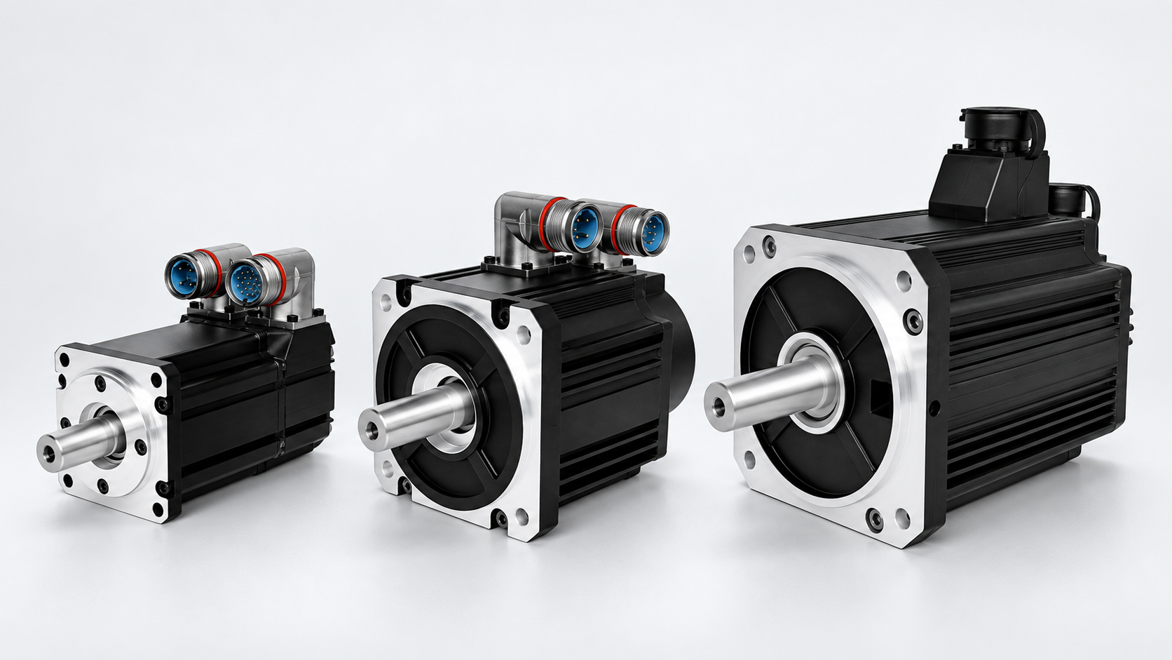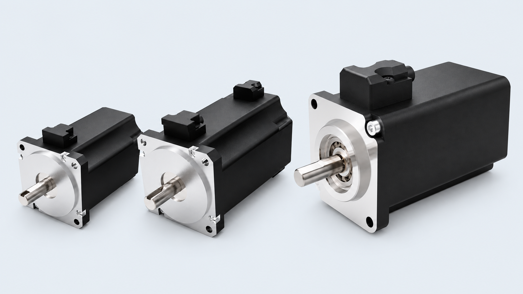
Inner-rotor construction
Low rotor inertia supports quick acceleration and responsive dynamic operation.
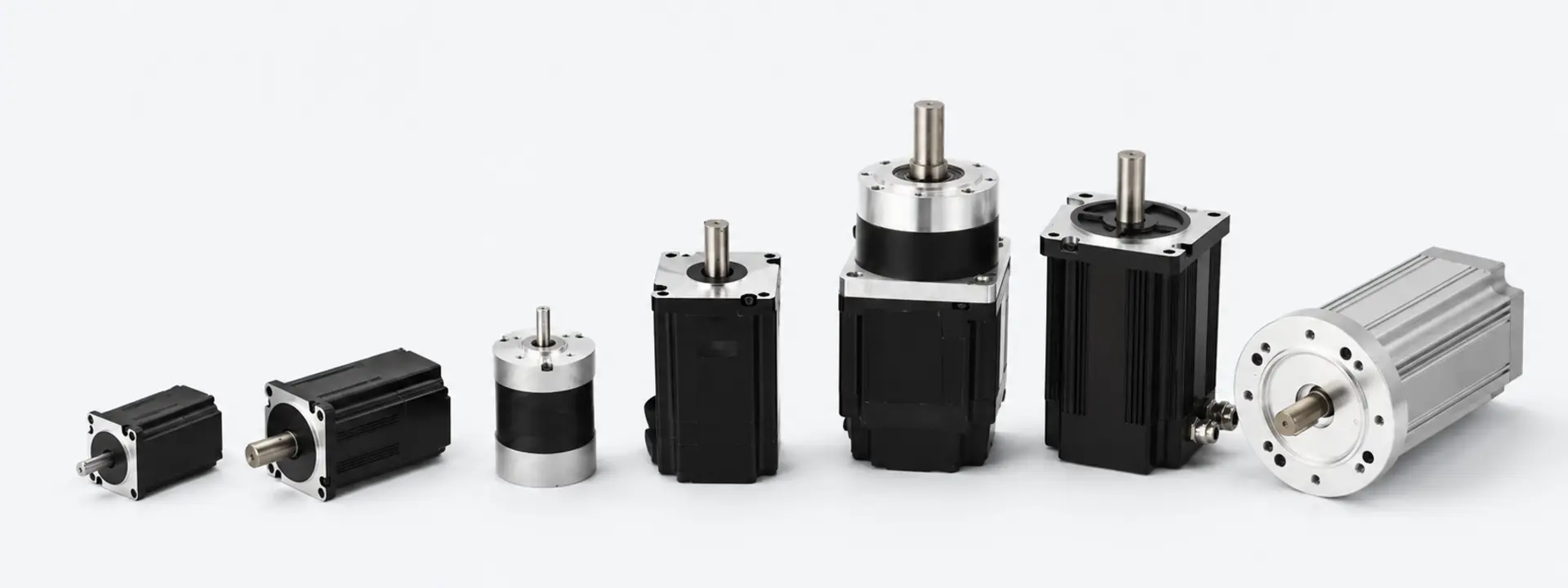
Select a platform for your application
SDT BL series brushless DC motors combine rare-earth magnets and aluminium housings with options for matched electronic drives, encoders and other feedback systems. Designed for quiet, efficient operation, they offer a range of continuous torque and speed capabilities for demanding applications where low noise and long service life matter.
| Motor example | Frame size (mm) | Typical voltage (VDC) | Rated output power (W) | Typical rated speed (rpm) | Continuous torque (N·m) | Peak torque (N·m) | Typical motor length (mm) |
|---|---|---|---|---|---|---|---|
| 24 | 12–24 | 5–15 | 3,000–8,000 | 0.01–0.04 | 0.03–0.10 | 30–50 | |
| 33 | 24–48 | 7–40 | 3,000–10,000 | 0.02–0.05 | 0.07–0.15 | 38–80 | |
| 42 | 24–36 | 25–125 | 3,000–4,000 | 0.06–0.30 | 0.18–0.90 | 40–90 | |
| 57 | 24–48 | 40–180 | 3,000–4,000 | 0.12–0.60 | 0.35–1.80 | 50–110 | |
| 60 | 24–48 | 50–200 | 3,000–4,000 | 0.15–0.60 | 0.45–1.80 | 50–120 | |
| 80 | 24–48 | 125–750 | 3,000–6,000 | 0.40–3.50 | 1.2–10.5 | 75–130 | |
| 85 | 24–48 | 110–800 | 1,000–3,000 | 0.35–2.50 | 1.0–7.5 | 55–135 | |
| 90 | 24–310 | 150–800 | 1,000–3,000 | 0.50–2.50 | 1.5–7.5 | 70–140 | |
| 110 | 48–310 | 500–3,000 | 1,000–3,000 | 1.6–9.5 | 5–29 | 85–230 | |
| 130 | 48–310 | 750–3,000 | 2,000–3,000 | 2.5–12 | 7–30 | 115–200 | |
| 150 | 48–320 | 3,000–6,000 | 1,500–3,000 | 16–24 | 35–60* | 175–260 |
Values shown are representative ranges across motor configurations. The limits within a row do not describe one simultaneous operating point. Final ratings depend on the selected winding, motor length, drive, cooling and duty. Alternative voltages, speeds, feedback systems, shaft configurations and mechanical arrangements are available to suit the application.
Beyond the standard range
For requirements outside the listed platforms, discuss a tailored motor and drive configuration with SDT. Dimensions and performance are confirmed against your specification.
Explore More →BL series construction
A scalable inner-rotor brushless platform developed for responsive, efficient and reliable operation.
Low rotor inertia supports quick acceleration and responsive dynamic operation.
Eight-pole construction is standard, with four-pole configurations available for higher-speed duties.
BL platforms cover compact fractional-power duties through higher-output solutions rated up to 6 kW.
High-energy neodymium rare-earth magnets support compact size, efficiency and torque density.
Selected windings and rotor configurations support operating speeds up to 20,000 rpm.
Class F and Class H winding-insulation systems are available to suit the thermal requirement.
IC410 non-self-ventilated construction, with precision rotor balancing to G2.5 where required.
Normally closed thermal-cutout protection can be incorporated for motor-temperature monitoring.
Configured to the application
Hall sensors, digital or SinCos encoders, absolute encoders and resolver feedback.
IP54 or IP65 configurations selected around the application and sealing requirement.
Holding brakes, matched gearheads and application-specific output arrangements.
Matched electronic drivers plus special mechanical, electrical and winding designs to customer specification.
Protection, cooling, insulation, balancing and thermal-protection arrangements are confirmed against the selected motor configuration and operating duty. Special designs can be developed to customer specification.
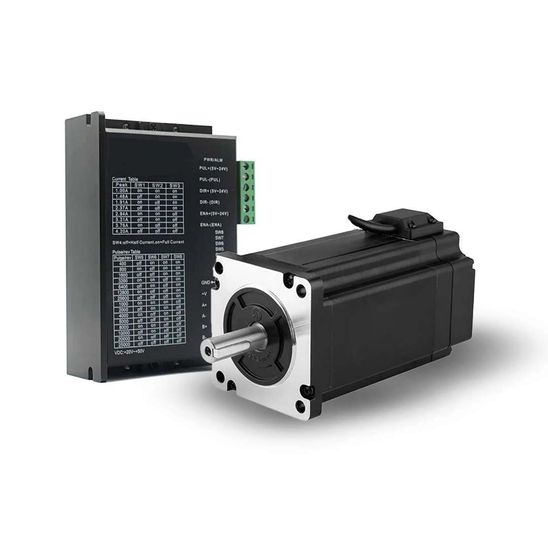
Part of the Brushless DC motor range
Compact two-quadrant controllers matched to Hall-sensor BL Series motors for dependable speed control, straightforward wiring and coordinated motor-and-controller supply.
Controller capabilities
Review the available control functions and confirm the controller against the motor, supply and operating duty.
Electronic speed control for Hall-sensor brushless motors, with efficient PWM output-stage operation.
Set speed from the internal potentiometer, an external potentiometer or an external voltage reference.
Dedicated inputs support direction selection, output-stage enable or disable, and controlled braking.
Maximum continuous current can be set using the controller's on-board potentiometer.
An internal thermal cut-out protects the controller against excessive operating temperature.
Specified for -10 to 45 °C operation and -40 to 85 °C storage.
Selection note: Controller voltage and current rating are matched to the selected motor, winding, operating point and duty cycle. Confirm the final combination with SDT before production release.
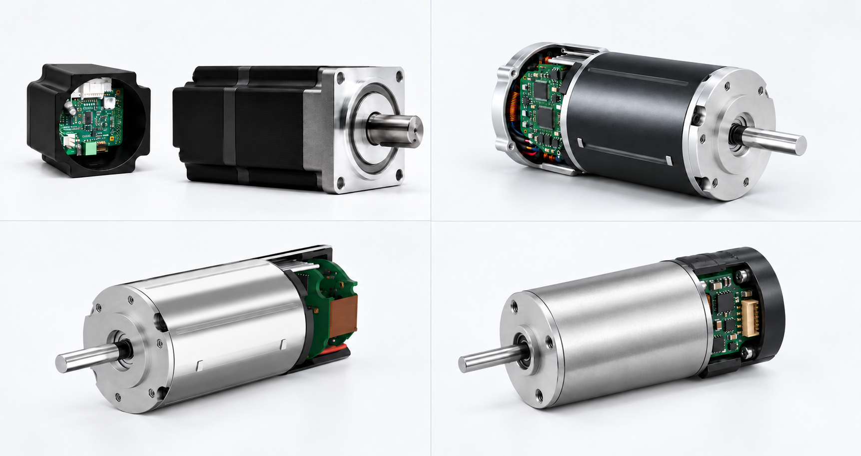
Motor and electronics as one system
Eight individual frame sizes—24, 40, 50, 60, 80, 90, 110 and 140 mm—provide engineering starting points for configured motor-and-control solutions. Frame diameter defines the platform; final torque, speed, voltage, power and controller configuration are confirmed around the equipment duty.
Extended high-performance range
Explore additional brushless platforms for precision servo control and high-dynamic coreless applications.
Reliable electronically commutated motion
Standard, modified or new
SDT starts with an established BLDC platform where it credibly meets the duty, then considers a controlled modification or an application-specific motor-and-drive development when the complete requirement demands it.
Learn MoreDefine the appropriate BLDC solution
Provide the input voltage, performance needs, envelope, feedback, operating environment and duty cycle.