
Electronic commutation
Motor phase switching coordinated with Hall, encoder or application-defined sensorless feedback.
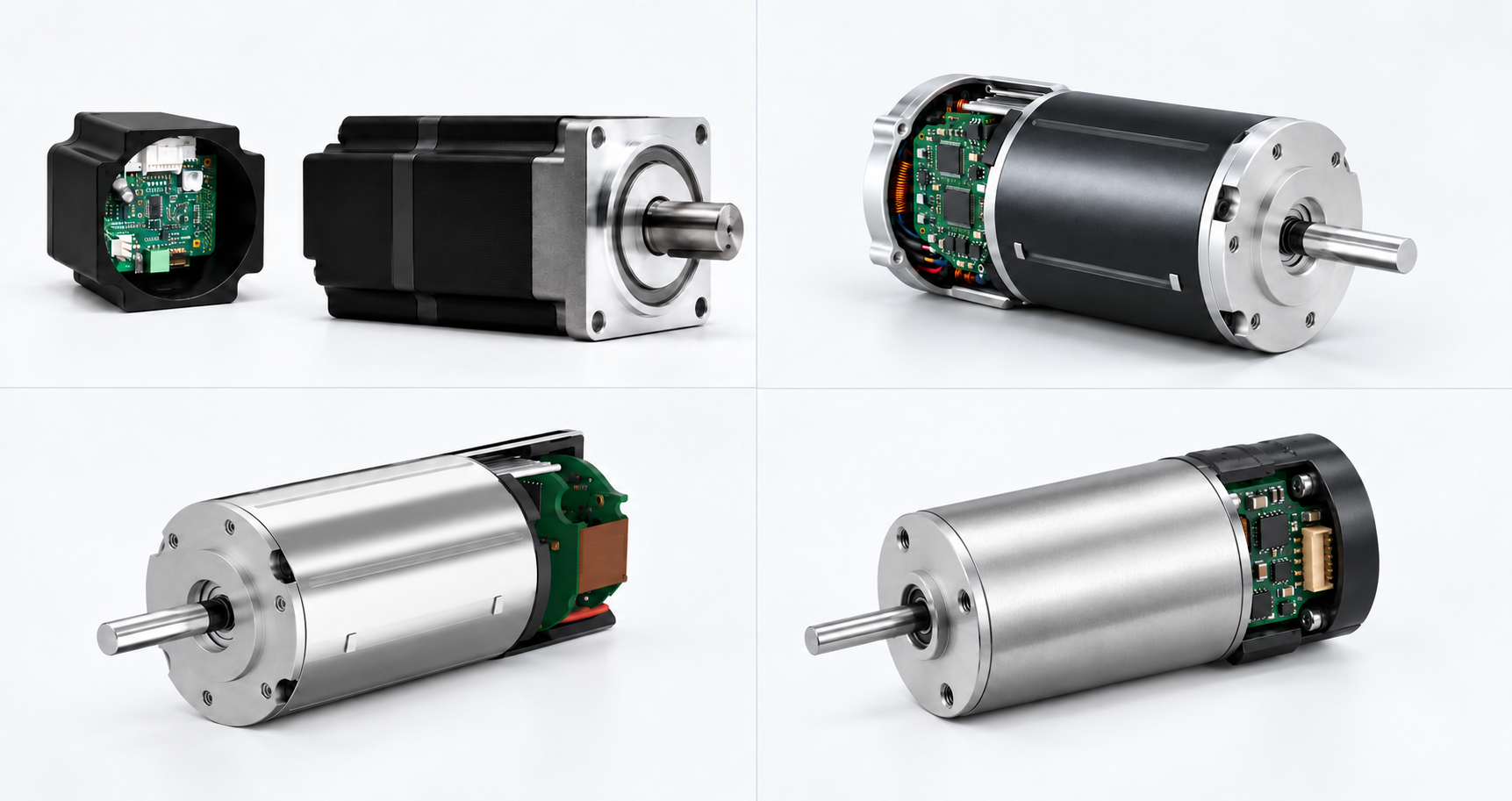
Why integrate the controller?
Integration can shorten wiring, reduce cabinet space and simplify machine assembly, but it also places electronics close to motor heat, vibration and the operating environment. SDT therefore treats the motor, controller, feedback, thermal path, protection and interface as one engineered system—not as a controller added after the motor has been selected.
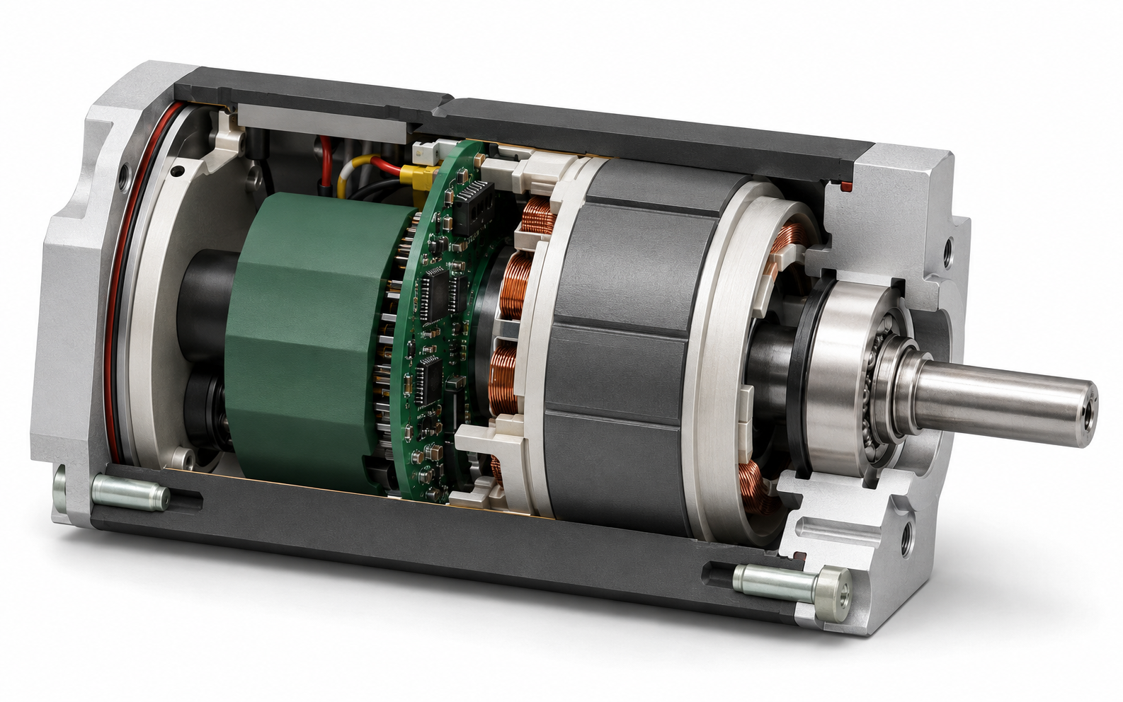
Integrated architecture
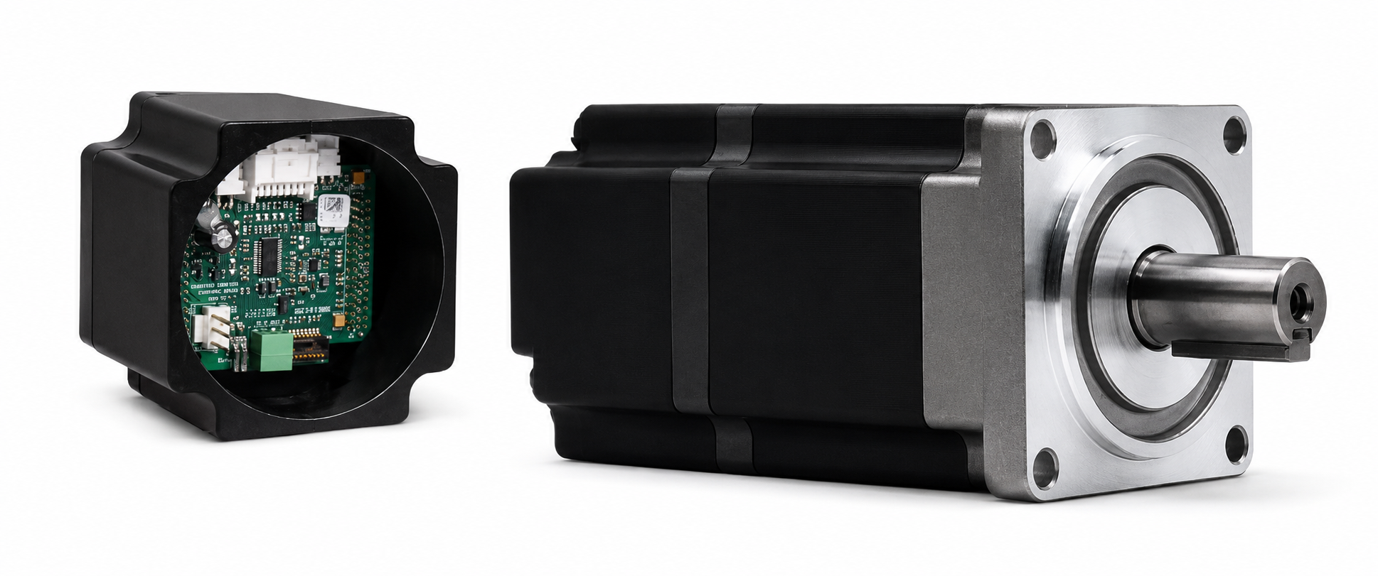
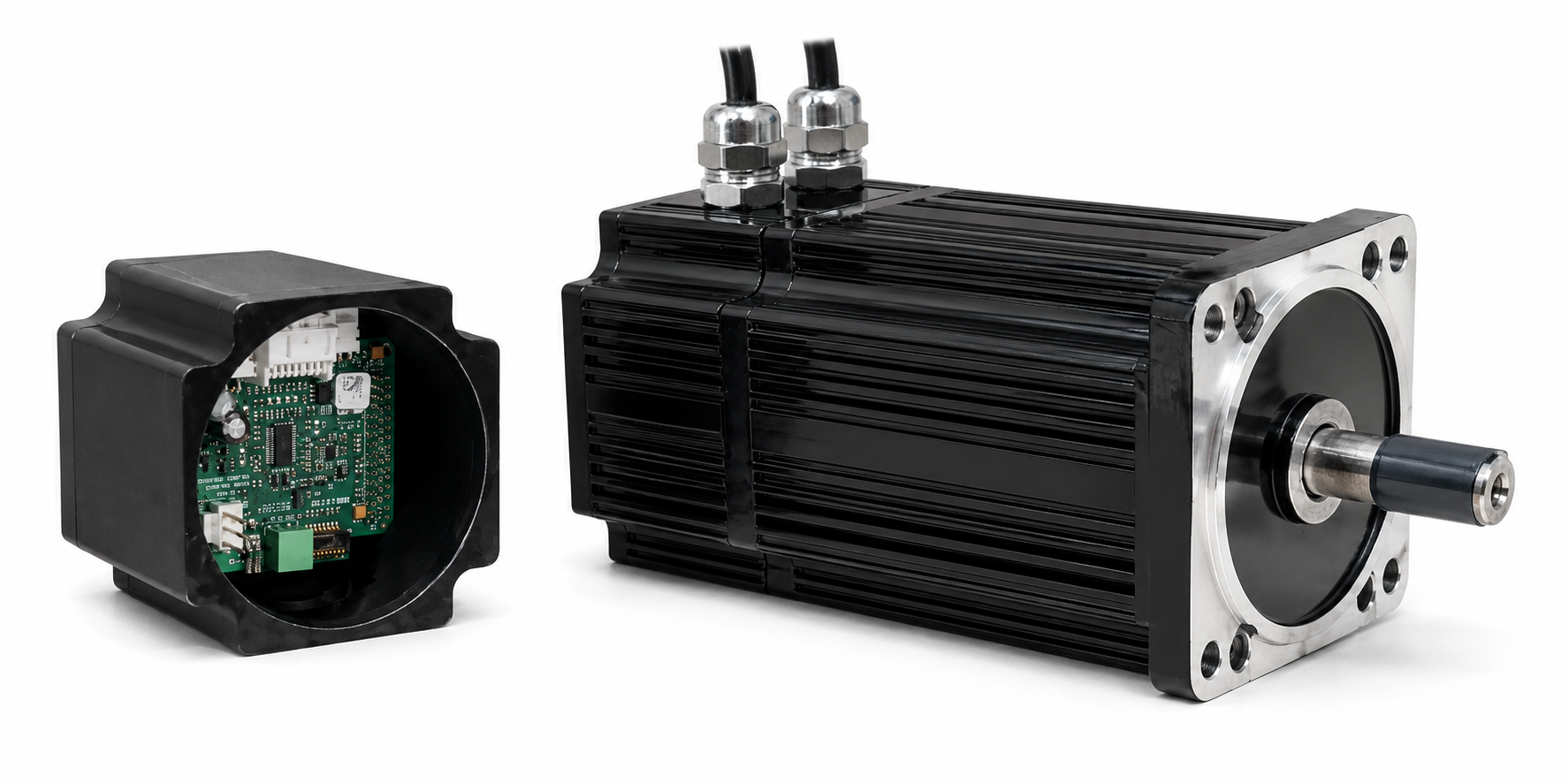
The cutaway shows how controller electronics can be packaged within the motor envelope while preserving the electromagnetic assembly, bearings and mechanical output interface.
Integrated-controller platforms
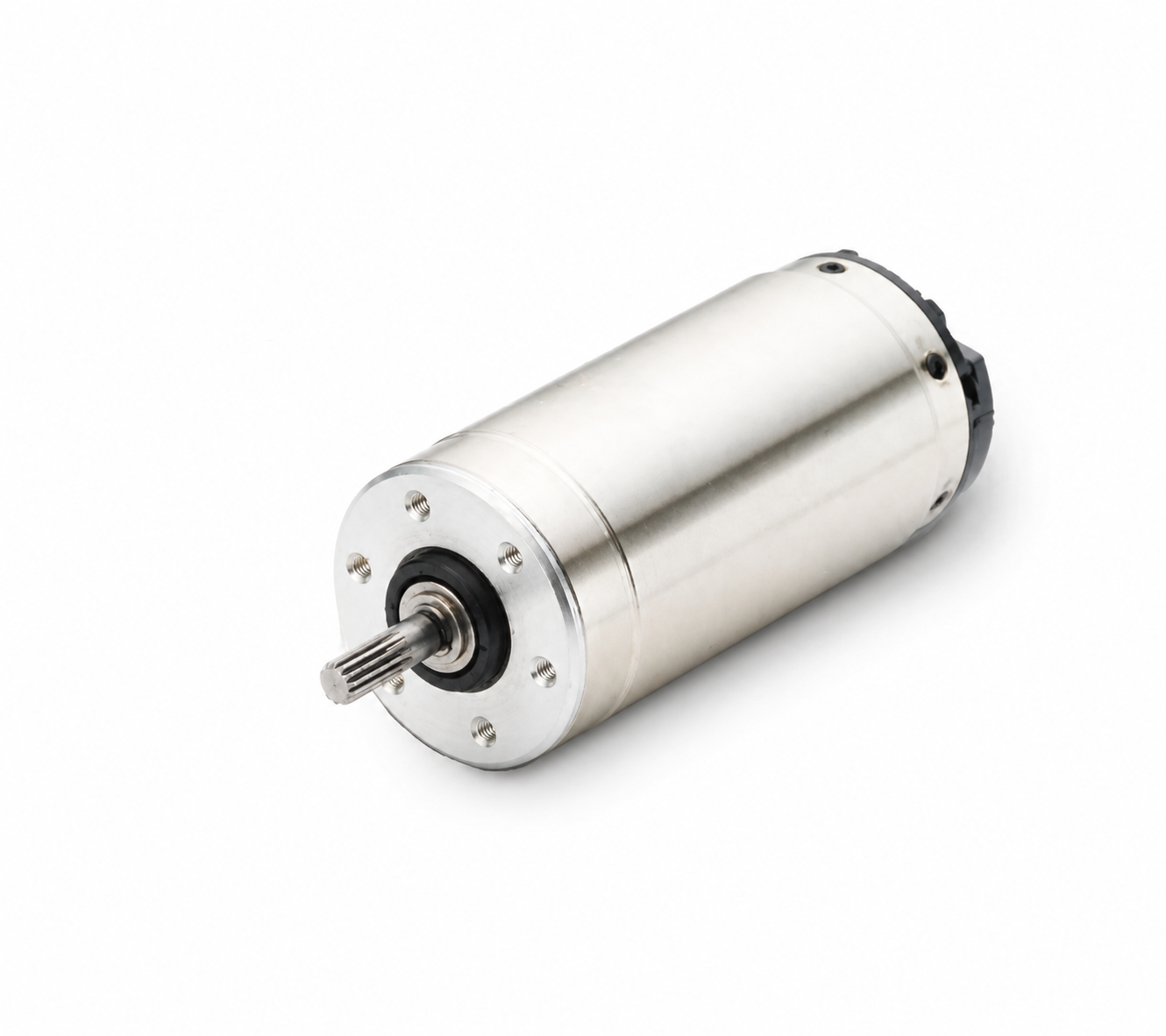
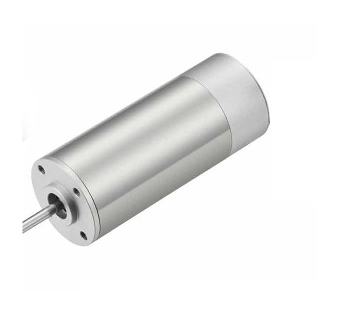
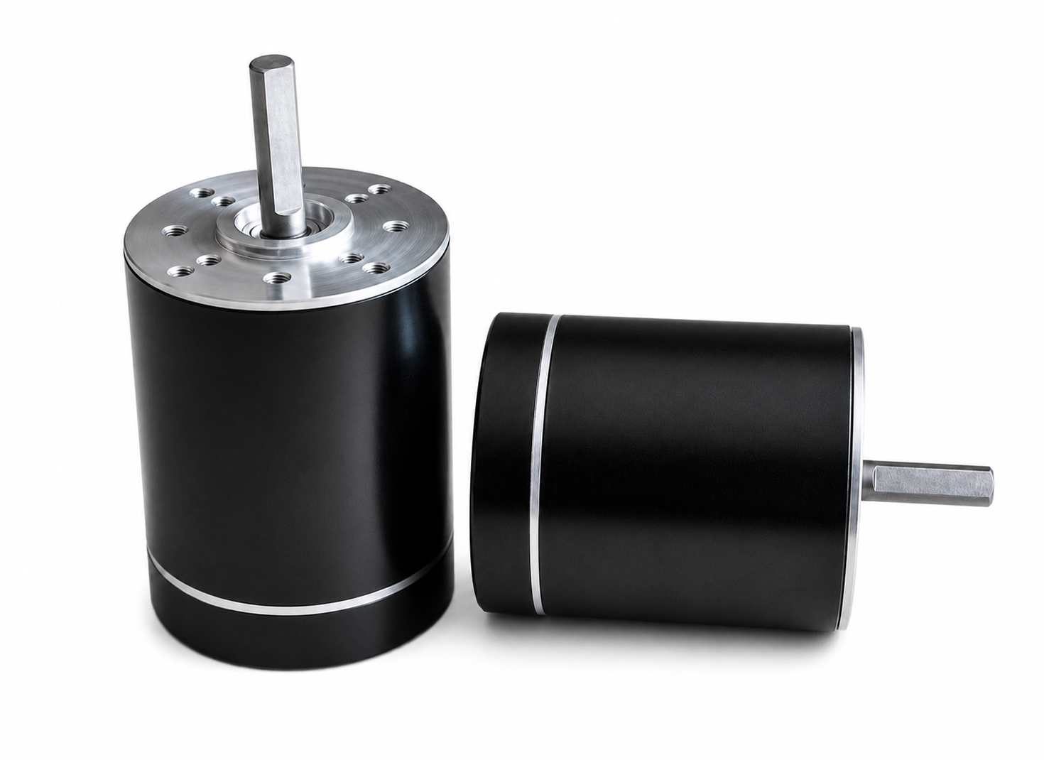
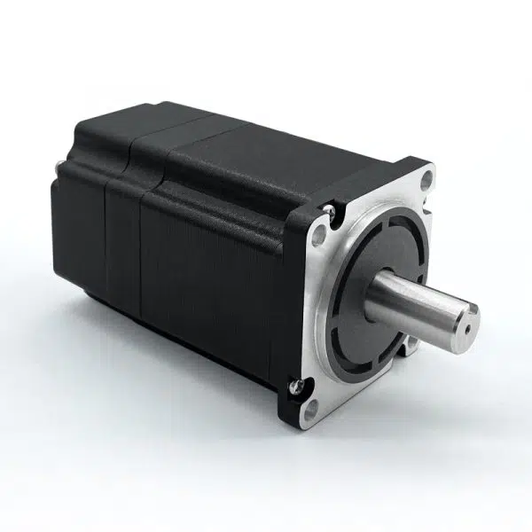
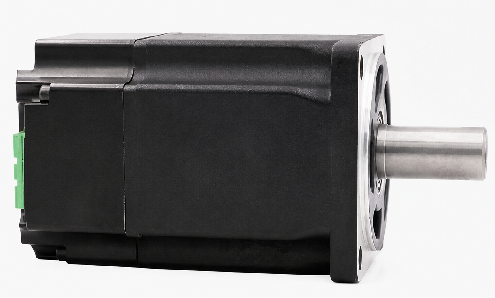
Explore the 24, 40, 50, 60, 80, 90, 110 and 140 mm platforms individually. Frame diameter defines the mechanical starting point; voltage, power, torque, speed, motor length and controller configuration are confirmed against the selected application.

Preliminary technical selection
The published source confirms an overall 0.012–0.35 N·m envelope for the earlier 24, 60, 80 and 90 mm family—not a rating for each frame. Individual voltage, current, torque, speed and power are released after the motor length, winding, controller, cooling and duty are selected.
| Frame | Mechanical platform | Controller arrangement | Technical release status |
|---|---|---|---|
| 24 mm | Miniature cylindrical | Integral drive | Published reference platform; rating released by selected motor length and winding |
| 40 mm | Compact cylindrical | Configured integrated route | Voltage, torque, speed and power released against the application |
| 50 mm | Cylindrical integral-drive | Integral electronic drive | Voltage, torque, speed and power released against the application |
| 60 mm | Cylindrical | Integral two-quadrant control | Published reference platform; rating released by selected motor length and winding |
| 80 mm | Square flange | Integrated electronics | Published reference platform; rating released by selected motor length and winding |
| 90 mm | Motor and controller | Integrated or adjacent control | Published reference platform; final package released against the application |
| 110 mm | Higher-output square flange | Matched open or integrated control | Motor, electronics and thermal arrangement released as one configured system |
| 140 mm | Large integrated platform | Coordinated housing and cooling | Motor, electronics and mechanical interface released as one configured system |
Technical architecture
The precise feature set follows the motor duty and equipment interface; not every function is included in every platform.
Motor phase switching coordinated with Hall, encoder or application-defined sensorless feedback.
The control mode, operating range and transient response are selected around the machine duty.
Hall sensors, encoders, direction, enable, braking, status and application-specific inputs can be reviewed.
Analogue commands, PWM, serial or fieldbus interfaces can be considered where the selected controller architecture supports them.
Current limiting, temperature monitoring, undervoltage, overvoltage and fault handling are defined with the electronics partner.
Controller housing, connector direction, sealing, shaft, flange and cooling provisions are coordinated as one package.
Commercial supply routes
Start with the lowest-complexity route that genuinely meets the equipment requirement. Hover, focus or tap each route for the engineering consequence.
Matched motor and controller engineering
Where the controller cannot be packaged within the motor envelope, SDT can engineer and validate the motor, feedback and controller as one matched system.
Application definition
Established suppliers publish detailed ratings for fixed series. SDT’s configured route starts by defining the operating envelope before committing the motor, electronics and package.
Nominal and maximum DC-bus voltage, available current and supply behaviour
Continuous and peak torque, speed range, acceleration and duty cycle
Speed, torque or position control; response, regulation and stopping behaviour
Hall, incremental or absolute encoder, resolver, sensorless operation or customer interface
Analogue, PWM, discrete I/O, serial or fieldbus requirement
Ambient temperature, ingress protection, vibration, EMC and regulatory context
Frame, length, shaft, mounting, connector access, gearbox, brake and cooling space
Prototype quantity, validation evidence, annual volume and lifecycle expectations
Suitable equipment duties
“Integrated controller” does not by itself define control quality, EMC compliance, protection level or environmental suitability. These depend on the selected hardware, software, feedback, enclosure, thermal design and validation plan.
Define the complete motor-and-control requirement
Share the voltage, torque-speed points, duty, feedback, communications, envelope, environment and expected production volume.